svg file
 svg file
 svg file
 svg file
 svg file
 pdf file
WARNING: in progress, not yet finished. But can be used for various output, as in photos below. You may need to fiddle around with various settings.
The point of this page is to provide a way to generate svg files for slice forms using javascript, since I couldn't find another such program out there, but there may well be one somewhere!
Slice forms are a well known way to make relatively low cost modles of surfaces, since they can simply be made from card or paper.
Examples of slide forms: papercraftetc blogspot, Elaine Wolfe; 3D prints, on "Yeggi" ; pintrest page; John Sharp pages; Google will give you many more. John Sharp has written some books. According to John Sharp, Sliceforms were invented by Olaus Henrici. Google refers me to an article by June Barrow-Green. I learned about slice forms from Laura Brady.
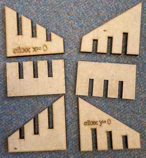
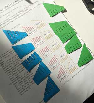
Click on the following images for some ready to use svg files; I made these to send to a laser cutting machine, but you could just print out and cut out. These are the very first output rough attempt! They were printed with the large red rectangle scaled to A1 size. I used lightburn and a laser cutter in Warwick's engineering build space. The cutter leaves burn marks on the paper. Use the program below to generate more svg files.
svg file
svg file
svg file
svg file
svg file
pdf file
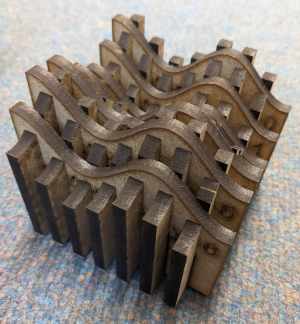
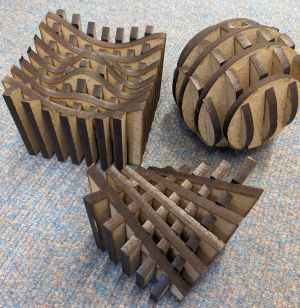
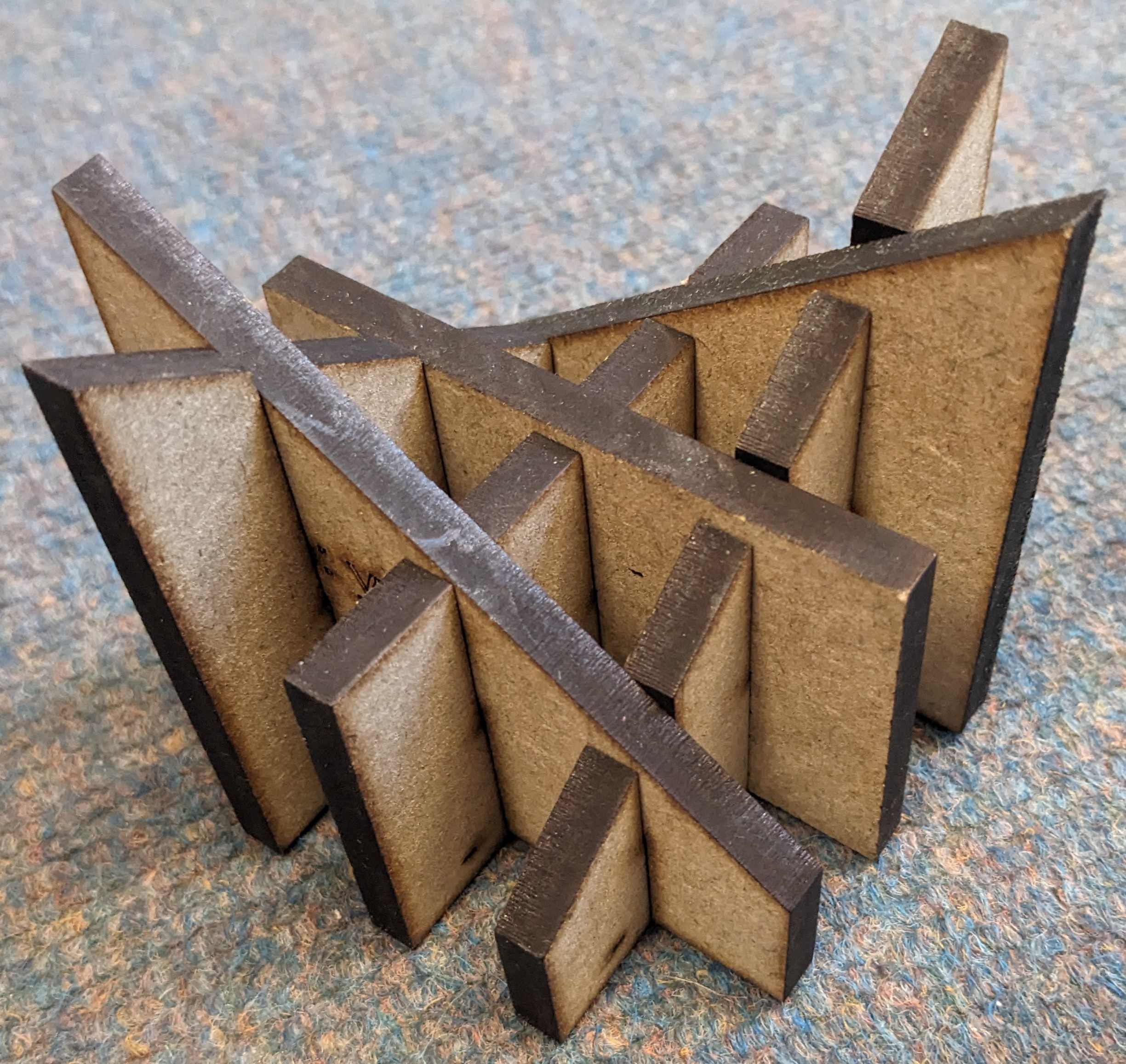
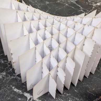
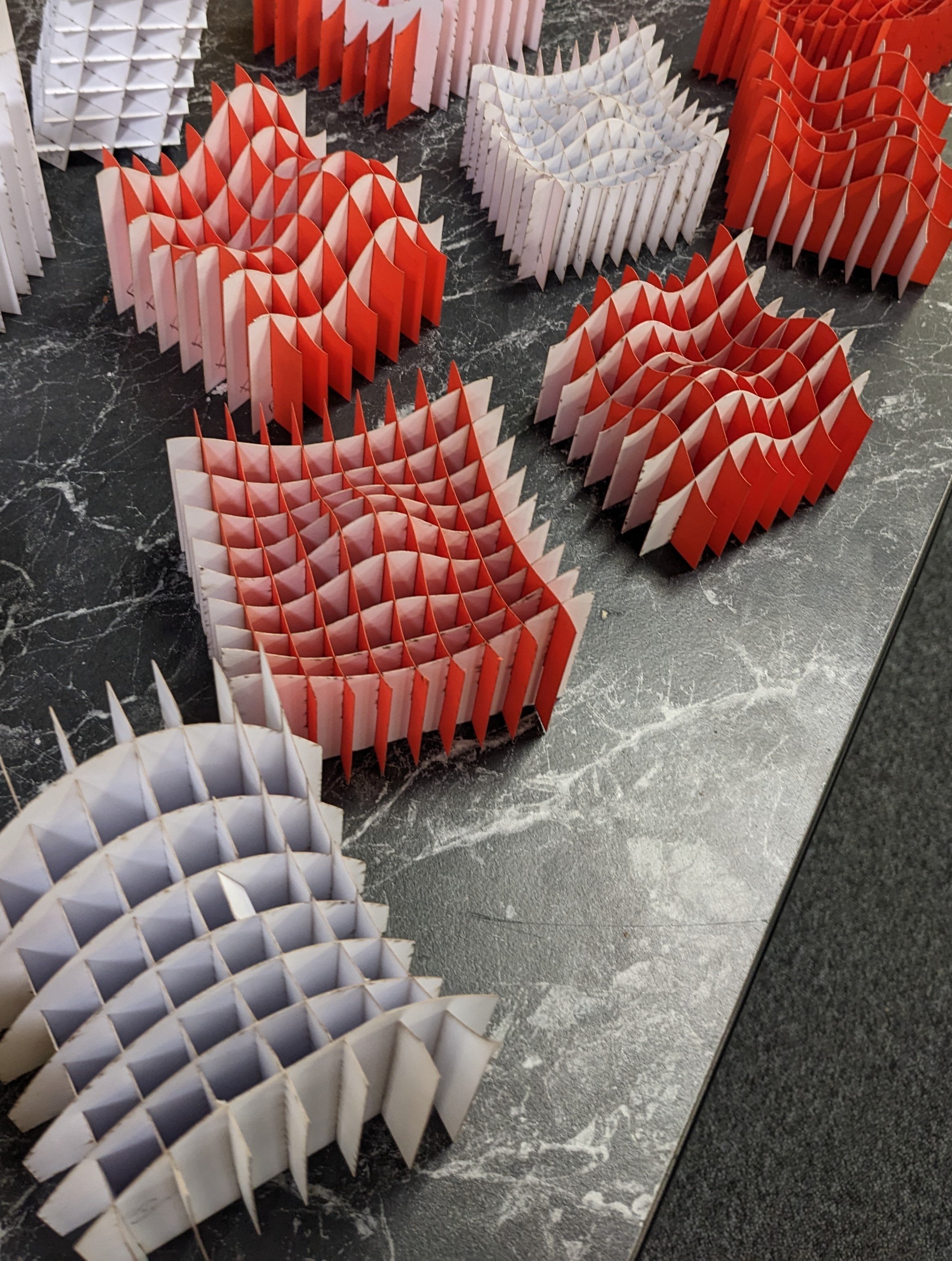
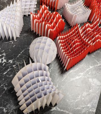
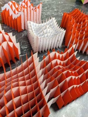
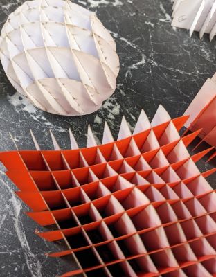
This is what they look like when made up. Some lovely undergraduates put these
together for me. The slots are 0.4mm thick mostly, which turns out to be maybe too small for easy slotting together (from thinish card), and too wide for them to hold together if not handled carefully. So, some other material might work out better.
This program is "in progress" and made in my spare time, and so does not have
all the possible features one might desire.
Some variables, controlled by the sliders (not all of which are currently implemented):
Currently maximum 20 slices; no particular reason not to have more, but probably should rewrite to place on sheets in a different way if there were more.
Distances on sliders are to be interpreted as in mm
(actually are just svg units).
Red outline is edge of a sheet of A1 card (594 x 841 mm), for reference;
user may need to open svg output in e.g., inkscape, and move shapes around for better fit in general case. Default is to allow a 8cmx8cm block for each slice
to print on.
Originally I'd planned to create two sheets, one for X=contant slices, and one
for Y=constant slices, which would
typically be printed on different card colours. However, in the end, I have
created a column of X=constant slices, and a column of Y=constant slices; the user can download the svg and use some other program to delete one or the other set of slices, and move round so they all fit on the sheet of A1.
Red lines and orange lines are both cut lines. Only reason for difference
is to distinguish easily between X and Y planes.
Magenta line round outside is for help with scaling to A1 size using lightburn. Can be removed for actual cutting, or left in if magenta is set to not cut.
Slices can be labled either by the values of the coordinates, or by the
number of the slice in a sequence. For putting together, the latter is more practical. For designing the slice form, the former may be useful as a reality check of what you are constructing.
The presets with the 6mm wide slits are for 6mm thick MFD. The 0.4mm wide
slots are for card.
The a, b, c, d parameters give a minimal amount of control for the curves.
For better control edit the code.
Space save version is designed for if you want to cut out a lot for a class,
and you don't want too much waste. This only has one variable function edge, the other is a straight line.